ZP19060 Keswick Vinyl Privacy Fence

ZP19060 Keswick Vinyl Privacy Fence Assembly Instructions

Approximate assembly time for two panels (60 minutes)
Click here to watch an installation video.
Introduction
General Information
Important Safety Notes:
- Check the inside of the larger pieces in your box for other materials packed inside.
- When assembling, place components on a non-abrasive surface (e.g., the shipping box) to avoid scratching.
- Use an area approximately 5′ × 8′ for unobstructed assembling.
- You should not need to use excessive force when assembling components.
Returns:
If you wish to return your product, please contact us first — we can often help resolve the issue right away.
If a return is still necessary, it must be initiated with the retailer where the product was purchased.
Need Help or Replacement Parts?
Although great care has been taken to ensure proper packaging and handling of this product, occasional issues can occur.
If you need replacement parts, assembly assistance, or have questions about the product, our customer service team is happy to help.
- Website: https://parts.nychbrands.com
- Email: support@zippity-outdoor.com
- Phone: 704-892-5222 or 877-234-6196
Customer service agents are available 9am–5pm EST, Monday–Friday.
For Quick Assistance:
- Have reference item number ZP19060
- Provide the specific part name
- Include the batch lot number stamped on the inside/end of the box
Product Specifications
Detailed Dimensions & Specifications
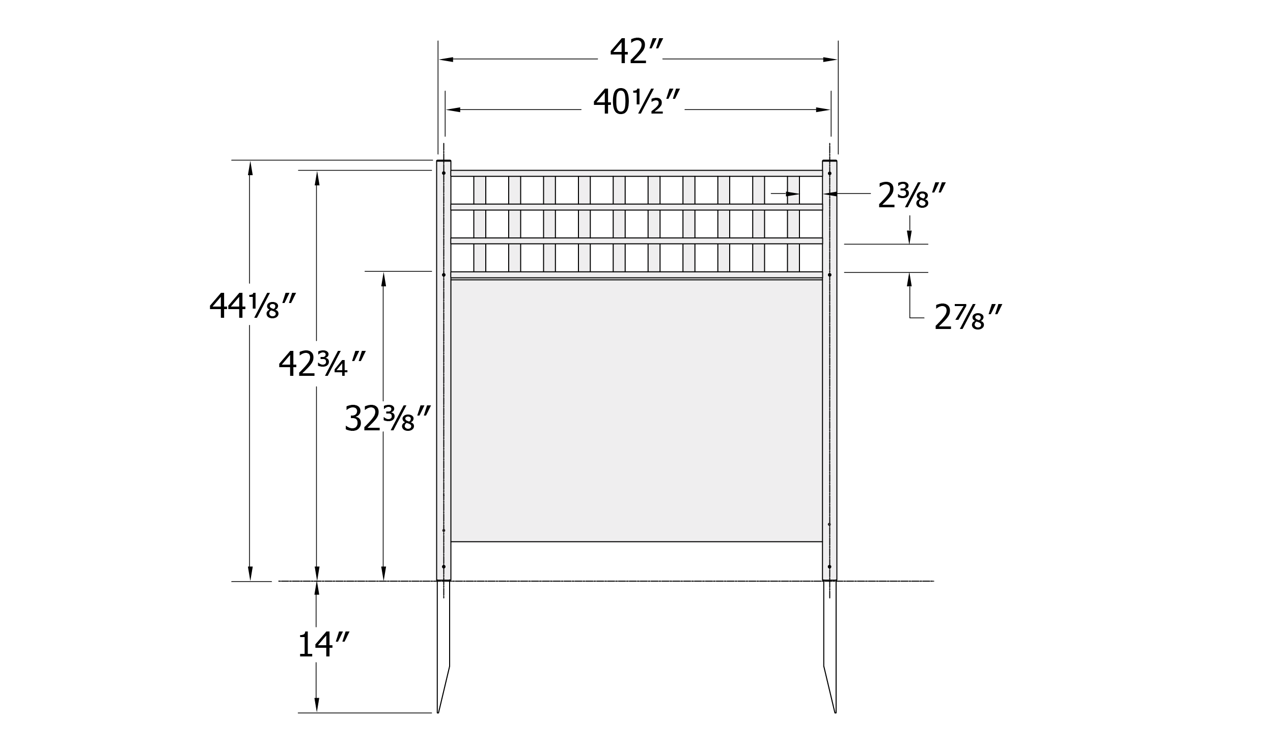
Product Specifications:
- Overall panel size: 44⅛″ H × 42″ W
- Approximate installed height to top of lattice: 42¾″
- Panel width between post centers: 40½″
- Ground stake depth into ground: 14″
Part Identification
A. Vertical Slat (20)

1/4" × 1¼" × 11⅛"
B. Ground Stake (4)

3/4" × 1¼" × 20"
C. Post Cap (4)

D. Left Post (2)

7/8" × 1½" × 44"
E. Right Post (2)

7/8" × 1½" × 44"
F. End Rail (4)
5/8" × 5/8" × 41⅞"
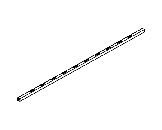
G. Middle Rail (4)

5/8" × 5/8" × 41⅞" (with routed holes for pickets)
H. Board – Narrow (2)
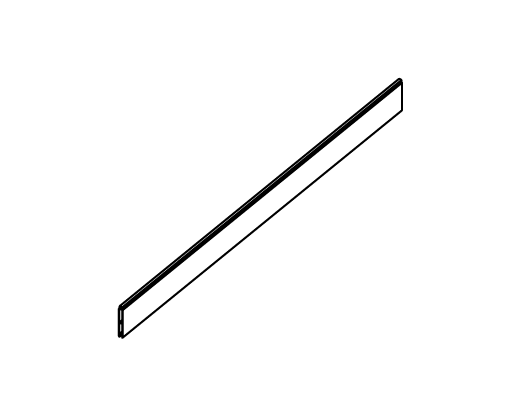
3/8" × 3" × 41¾"
I. Board – Wide (6)
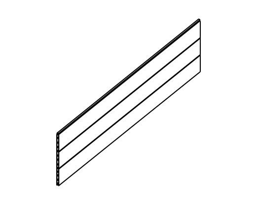
3/8" × 8½" × 41⅞"
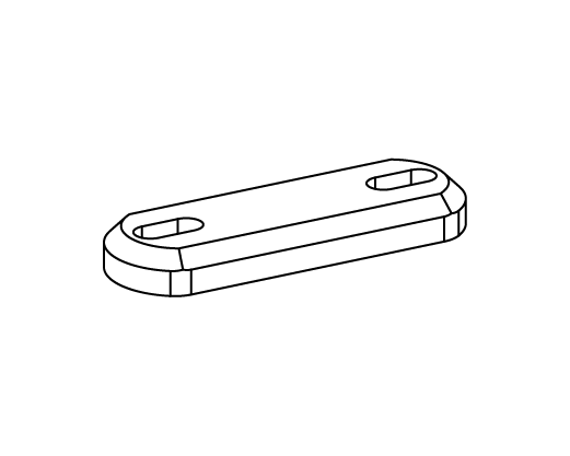
J. Zippity Joiner Clip (4)
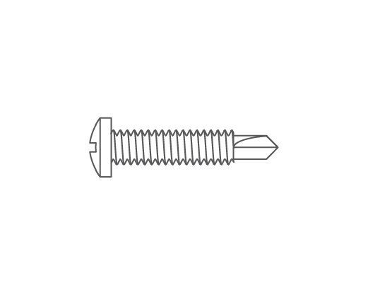
K. ¾" Self-Drilling Stainless Steel Screw (24)
Assembly Step 1 — Lay Out Materials

- Check the inside of the larger pieces in your box for other materials packed inside.
Assembly Step 2 — Install Ground Stakes

- Insert two Ground Stakes (B) into the bottom of the Left Post (D) and Right Post (E).
- Slide the ground stakes up into the posts until the pre-drilled holes in the stakes align with the pre-drilled holes in the posts.

- Drive (2) ¾″ Self-Drilling Stainless Steel Screws (K) into the lowest pre-drilled holes on each post to secure the stakes.
Assembly Step 3 — Install Boards

- Lay out (1) Left Post (D) and slide (1) Narrow Board (H) into the bottom of the routed grooves in the post.

- Insert (3) Wide Boards (I) into the slots in the post above the narrow board.

- Drive (1) ¾″ self-drilling stainless steel screw (K) into the second-lowest pre-drilled hole on the left post to secure the boards.
Assembly Step 4 — Assemble Lattice Top

- Insert (10) Vertical Slats (A) into the routed holes in the Middle Rails (G)

- Place (1) End Rail (F) over the top of the picket tabs as shown
- Note: Middle rails (G) have picket holes on both sides.

- Place the second End Rail (F) over the bottom of the pickets to complete the lattice top assembly.
Assembly Step 5 — Assemble Panels
Step 5.1 — Attach Lattice Top to Left Post

- Slide the assembled lattice top into the routed holes in the Left Post (D)
- Drive (2) ¾″ self-drilling stainless steel screws (K) into the pre-drilled holes in the post to secure the lattice top
Step 5.2 — Attach Right Post

- Starting from the bottom of the Right Post (E), slide the routed holes of the post over the boards and rails
- Ensure all boards and rails are fully seated into the right post
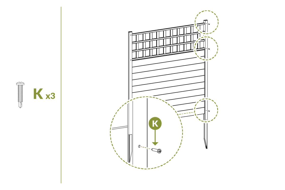
- Drive (3) ¾″ self-drilling stainless steel screws (K) into the pre-drilled holes in the right post to secure the assembly.
Assembly Step 6 — Assemble Second Panel

- Repeat Steps 2–5 to assemble the second panel.
Assembly Step 7 — Install Panels into Ground
Step 7.1 — Set Panel Position

- Move the assembled panel to its final location and identify the positions of the posts.
- Attempt to push the panel into the ground as illustrated.
Step 7.2 — For Hard Ground (Optional)

Complete only if the ground is too hard to push the panel in by hand.
- Loosen the top 4″ of soil with a claw hammer or similar tool.
- Add water to further loosen the soil if necessary.
- Place a block of wood over the top of each post to protect it and gently hammer the post into the ground until fully seated.
Assembly Step 8 — Connect the Panels

- Straight-line application: Install Zippity Joiner Clips (J) between adjacent posts as shown to align the panels in a straight run.

- Corner application: Install Zippity Joiner Clips (J) as shown to create a corner between panels.
Assembly Step 9 — Install Post Caps

- Insert Post Caps (C) over the posts to complete the installation.
Need Help?
- Email: support@zippity-outdoor.com
- Phone: 704-892-5222 or 877-234-6196
- Text: 980-580-6508
